ULN2803ADWR
ULN2803ADWR Introduction
ULN2803ADWR is an 8-channel Darlington transistor array produced by Texas Instruments (TI). It is mainly used to drive high-current, high-voltage loads such as relays, solenoid valves, LED displays, stepper motors, etc. The device uses a high-density package and can control high-current devices through low-voltage signals.
ULN2803ADWR Parameters
ULN2803ADWR Similar Prodcuts Comparison
ULN2803ADWR vs ULQ2003ATDRQ1 vs MCP23S08-E/SO vs ULN2004ADR vs ULN2004AD Comparison
| Parameter | ULN2803ADWR | ULQ2003ATDRQ1 | MCP23S08-E/SO | ULN2004ADR | ULN2004AD |
|---|---|---|---|---|---|
| Image | 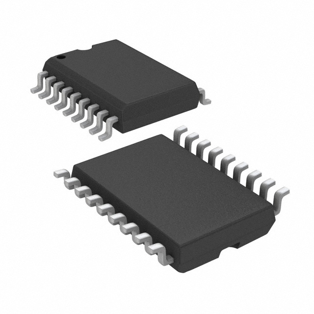 | 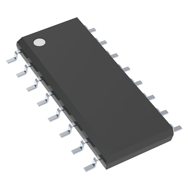 |  | 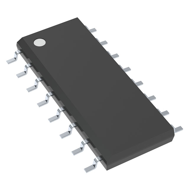 | 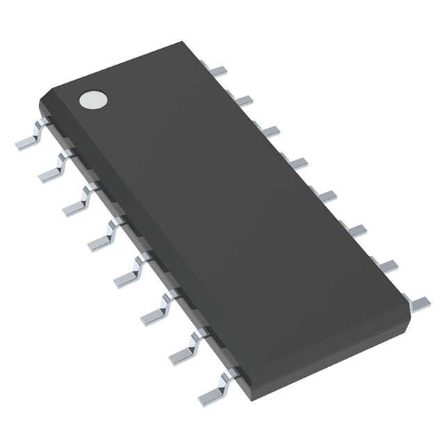 |
| Manufacturer | Texas Instruments | Texas Instruments | Microchip Technology | Texas Instruments | Texas Instruments |
| Type | Darlington Transistor Array | Darlington Transistor Array | I/O Expander (SPI Interface) | Darlington Transistor Array | Darlington Transistor Array |
| Channels | 8 channels | 8 channels | 8 channels (I/O ports) | 4 channels | 4 channels |
| Input Type | TTL-compatible inputs | TTL-compatible inputs | SPI interface for control | TTL-compatible inputs | TTL-compatible inputs |
| Output Type | Open collector (sink) | Open collector (sink) | Push-pull outputs (for GPIO) | Open collector (sink) | Open collector (sink) |
| Output Current | 500 mA per channel (max) | 500 mA per channel (max) | 25 mA per I/O pin | 500 mA per channel (max) | 500 mA per channel (max) |
| Voltage Rating | 50V maximum | 50V maximum | 5.5V maximum | 50V maximum | 50V maximum |
| Saturation Voltage | 1.4V (typical) | 1.4V (typical) | N/A | 1.4V (typical) | 1.4V (typical) |
| Power Supply | 5V to 30V (for input) | 5V to 30V (for input) | 2.7V to 5.5V | 5V to 30V (for input) | 5V to 30V (for input) |
| Package Type | SOIC-20 | SOIC-20 | SOIC-8 | SOIC-16 | SOIC-16 |
| Operating Temperature | -40°C to +85°C | -40°C to +125°C | -40°C to +85°C | -40°C to +85°C | -40°C to +85°C |
| Internal Diodes | Yes (for inductive load protection) | Yes (for inductive load protection) | No internal diodes | Yes (for inductive load protection) | Yes (for inductive load protection) |
| Typical Applications | Driving relays, lamps, motors | Driving relays, lamps, motors | Expanding GPIOs over SPI | Driving relays, lamps, motors | Driving relays, lamps, motors |
If you need to drive high-current inductive loads (such as relays, motors, or lamps), ULN2803ADWR, ULQ2003ATDRQ1, ULN2004ADR, or ULN2004AD are the appropriate choices.
If you need to expand the number of GPIOs in your system over SPI, the MCP23S08-E/SO is the best option, but it is not suitable for driving high-current loads.
ULN2803ADWR application
Relay drive: can directly control the switching operation of the relay.
LED drive: suitable for driving LED matrix displays or multi-channel LED lights.
Solenoid valve control: used for solenoid valve control in industry and automation.
Stepper motor drive: drive stepper motors simultaneously through multiple channels.
ULN2803ADWR working principle
ULN2803ADWR consists of 8 Darlington transistor pairs inside, each pair has high gain characteristics, which enables low-level control signals to drive high-current loads.
The logic level input is directly coupled with the output, and the input signal can be TTL or CMOS logic level. Each channel output can drive a load, suitable for multiple parallel control applications.
ULN2803ADWR Pin Diagram and Function
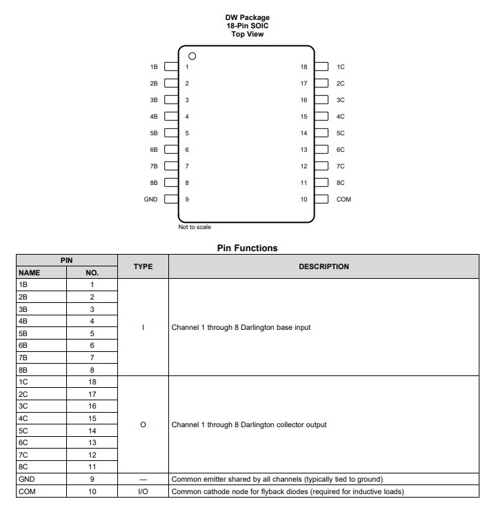
ULN2803ADWR PDF Datasheet and Reference Manual
Download datasheets and manufacturer documentation for ULN2803ADWR
ULN2803ADWR Q&A
1. What is ULN2803ADWR?
A: ULN2803ADWR is an 8-channel Darlington transistor array produced by Texas Instruments. It is suitable for driving high current, high voltage loads such as relays, LEDs, stepper motors and solenoid valves. Each channel can handle up to 500 mA, suitable for multiple parallel drive applications.
2. What is the maximum output current of ULN2803ADWR?
A: The maximum output current of each channel is 500 mA. Multiple channels can be used in parallel to obtain higher current, but it is necessary to ensure heat dissipation and total power limit.
3. What devices is the ULN2803ADWR suitable for driving?
Answer: The ULN2803ADWR is suitable for driving high-current, high-voltage loads, including:
Relays
Stepper motors
Solenoid valves
LED arrays
Buzzers
Inductive loads (such as motors)
4. What is the input logic level of the ULN2803ADWR?
Answer: The ULN2803ADWR is compatible with TTL and CMOS logic levels, and the typical input logic level is 5V. When the input is high, the transistor turns on and drives the load.
5. Does the ULN2803ADWR have built-in protection?
Answer: Yes, the ULN2803ADWR has an internal reverse voltage protection diode for driving inductive loads (such as relays and motors). This helps absorb the reverse electromotive force generated by the inductive load and protect the device from damage.
6. Can the ULN2803ADWR be used in parallel?
A: Yes, multiple channels of the ULN2803ADWR can be used in parallel to obtain higher output current. However, to ensure that the total output current does not exceed the thermal limit of the package, it is generally recommended that the current per channel does not exceed 500 mA.
7. What is the package form of the ULN2803ADWR?
A: The package form of the ULN2803ADWR is SOIC-18 (wide body package), which is suitable for surface mount (SMD) applications. There are also other package forms, such as DIP package, which is suitable for different types of circuit boards.
8. What is the difference between the ULN2803ADWR and the ULN2003?
A: The main difference is the number of channels:
The ULN2803 has 8 channels, while the ULN2003 has only 7 channels.
Both are similar in structure and function, both are Darlington array drivers, and support the same current and voltage specifications.
9. What is the operating voltage range of the ULN2803ADWR?
A: The operating voltage of ULN2803ADWR can be up to 50V. The input end is compatible with low voltage logic, while the output end can be connected to high voltage loads, usually for 12V or 24V load driving.
10. How to connect ULN2803ADWR to a microcontroller?
A: The input end of ULN2803ADWR can be directly connected to the digital output pin of the microcontroller, and the typical control level is 5V. When the pin of the microcontroller outputs a high level, the corresponding Darlington pair of ULN2803ADWR will be turned on, and the output end drives the connected load.
11. How many output channels does ULN2803ADWR support?
A: ULN2803ADWR provides 8 independent output channels. Each channel can independently drive a load, which is suitable for multi-channel parallel control applications, such as LED display matrix or multi-way relay control.
12. Can ULN2803ADWR drive stepper motors?
A: Yes, the ULN2803ADWR is well suited for driving the coils of a stepper motor. Through multi-channel parallel control, the ULN2803ADWR is able to precisely switch the windings of the stepper motor to meet the control requirements of the stepper motor.
13. Can the ULN2803ADWR be used for PWM control?
A: Yes. The ULN2803ADWR can be used for PWM (Pulse Width Modulation) control, which is suitable for applications such as adjusting LED brightness or motor speed control. Simply input the PWM signal to the input of the ULN2803ADWR, and it will adjust the output load based on the duty cycle of the PWM signal.
14. What are the alternatives to the ULN2803ADWR?
A: Some alternatives include:
ULN2003: 7-channel Darlington array for applications with fewer channels.
TBD62083AFG (Toshiba): 8-channel Darlington array with similar functions and performance.

