What are the basic principles and common types of optical isolators?
Optical isolators are widely used in fiber optic communication systems, fiber optic sensing systems, and fiber optic lasers. The basic and common principle of optical isolators is the Faraday effect. However, the device structure and characteristics are variable, as follows.
1. Free-space optical isolator
The structure of the free-space optical isolator is shown in Figure 1, which includes two polarizers, a Faraday rotator (FR), and a magnetic ring. The transmission axes of the two polarizers are aligned at a 45° angle, and the FR has a fixed rotation angle of 45° in a saturated magnetic field.
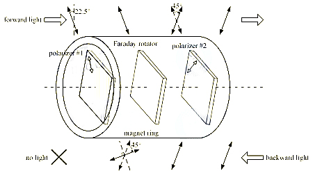
Figure 1 Free-space optical isolator structure
For forward light (linear polarization LP), it first passes through polarizer #1 and is rotated by FR. Because the light vector is aligned with the transmission axis, it passes through polarizer #2 with little loss. For backward light, it first passes through polarizer #2 and then rotates by FR, but because the light vector is perpendicular to the transmission axis, it is finally blocked by polarizer #2. The above principle shows that the forward light is allowed to pass, while the backward light is isolated.
Free space isolators have the characteristics of simple structure and low cost, but their polarization dependence limits their applications. It requires the forward light to be LP polarized and the light vector to be aligned with the first polarizer. Therefore, it cannot be used in-line (fiber) because the SOP (state of polarization) of the optical signal in the fiber is random. The main application of free space isolators is laser diodes (LD).
FP LD (Fabry-Perot laser diodes) emit randomly polarized light, while DFB LDs (distributed feedback laser diodes) emit LP light. Compared with FP LDs, DFB LDs have better monochromaticity, higher output power, and higher modulation rate, which makes them more promising for application. In optical transmitters, free space isolators are placed between the DFB LD chip and the optical fiber. Any back-reflected light from the optical fiber line is isolated to prevent damage to the LD chip.
2. BD-type optical isolators
In-line applications (such as EDFA) require polarization-independent optical isolators that can pass forward light with any SOP. The first polarization-independent optical isolator is based on a beam displacer (BD), as shown in Figure 2. It consists of two BDs, one FR, one HWP (half-wave plate), a magnetic ring, and two fiber collimators.
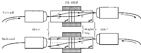
Figure 2 Optical isolator based on beam displacer, FR-Faraday rotator, HWP-half-wave plate, BD-beam displacer
The forward light from the input collimator is incident on the first BD. It is laterally separated into o-ray and e-ray in the BD block. The two rays pass through the FR+HWP component, and the SOP is transformed into e→o and o→e. The two rays are recombined by the second BD block and finally received by the output collimator. Therefore, the forward light can pass through.
The BD-based isolator can pass any SOP forward light with two BDs to achieve polarization diversity. Therefore, it is called a polarization-independent optical isolator.
It should be noted that due to the asymmetric separation of light by the BD block, the input and output fiber collimators are not coaxial, which is not convenient for the assembly and packaging of the device. In fact, the coaxial design can be achieved by the optimized BD we mentioned earlier.
Due to the lateral displacement of the light in the first BD block, the backward light is isolated. The relationship between the calculated ray isolation and the lateral displacement is shown in Figure 3. The light in the BD block needs to be separated by 0.6mm to obtain an isolation of 40dB. Uniaxial crystal YVO4 is widely used to make BD blocks due to its high birefringence. The maximum deviation ratio of o-ray to e-ray is d:L=1:10 (d is the lateral interval between the two rays, and L is the length of the BD block), which means that the minimum BD length is 6mm. YVO4 is large in size and expensive. Therefore, BD-type optical isolators are rarely used in optical fiber communication systems, which have the greatest demand for optical isolators.
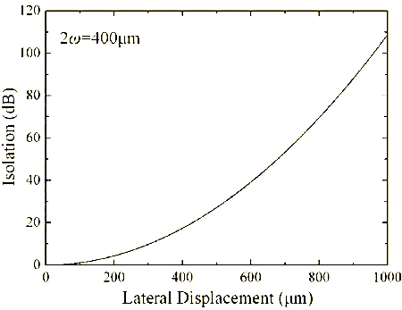
Figure 3 Relationship between ray isolation and lateral displacement
3. Wedge-shaped optical isolator
The structure of the wedge-shaped optical isolator is shown in Figure 4. It includes two fiber collimators and an isolator core. The core structure is shown in Figure 5, including two birefringent wedges, a 45° FR and a magnetic ring.
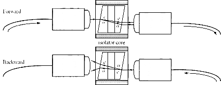
Figure 4 Wedge-shaped optical isolator structure
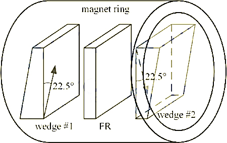
Figure 5 Wedge-shaped optical isolator core structure
The optical axes of the wedges are all parallel to the right-angle plane, and the intersection angle of the directions is 45°, as shown in Figure 5. The forward natural light from the first collimator is split into o-ray and e-ray in wedge #1. Then the light vector rotates 45° after passing through FR. When the two rays enter wedge #2, they remain as o-ray and e-ray. Therefore, the SOP transformations of the two rays in the two wedges are o→o and e→e, respectively. The refractive index of each ray remains unchanged. The entire isolator core acts as a parallel plate for the forward light. The rays pass through the plate obliquely and remain parallel to each other. Each ray has a lateral offset, and the walk-off (the difference between the offsets of the two rays) is small (~10μm). The two rays are received by the second collimator with little loss.
For the backward light, the SOP transformations of the two rays in the two optical wedges are o→e and e→o, respectively. The isolator core acts as a Wollaston prism for the backward light. Both rays have an angular deviation and cannot be received by the input collimator. The relationship between ray isolation and angular deviation is shown in Figure 6. The isolation increases rapidly with the increase of angular deviation. An angular deviation of 0.5° is enough to isolate the backward light by 50dB.
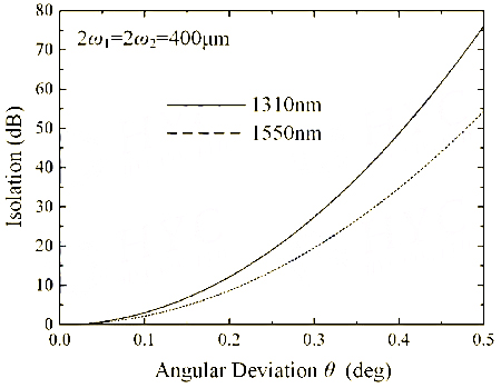
Figure 6 Relationship between ray isolation and angular deviation
In fact, the isolation of the wedge optical isolator is limited by the extinction ratio (ER) of the FR. The typical ER of commercial FR is 40dB, which means that when the light vector of the LP light is rotated to the x-axis, 1/10000 optical power is detected when the transmission axis of the polarizer is aligned with the y-axis. The ER of the FR limits the maximum isolation to ~40dB.
4. Double-stage optical isolator
In some special applications that require higher isolation, a double-stage optical isolator is required. There are 3 typical structures of double-stage wedge optical isolators.
- Structure #1
Figure 7 shows the structure #1 of the double-stage isolator core, which consists of two isolator cores rotated 45° relative to each other. Therefore, for the forward light, the SOP transformations of the two rays in the four wedges are o→o→e→e and e→e→o→o, respectively. The double-stage isolator core acts as two parallel plates for the forward light, although the main part of the two plates has a 45° crossing angle. The two rays pass through the plates obliquely and remain parallel to each other. Each ray has a lateral offset and a small walk-off (~15μm). The output collimator receives the two rays with little loss.
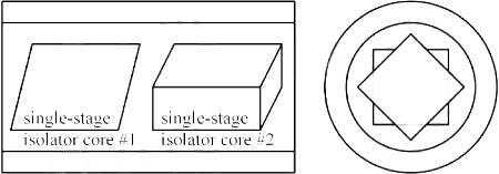
Figure 7 Core structure of double-stage wedge optical isolator #1
For the backward light, the SOP transformations of the two rays in the four wedges are o→e→o→e and e→o→e→o, respectively. The isolator core acts as two Wollaston prisms. The angular deviation of the two rays is larger than that in the single-stage isolator. In fact, the improvement in isolation is not due to the larger angular deviation of the backward light. An additional FR doubles the ER.
The double-stage optical isolator in Figure 7 can achieve high isolation. However, since the relative 45° rotation between the two isolator cores always introduces unexpected scattering on the backward light and reduces the isolation of the device, the assembly efficiency and yield are not good.
- Structure #2
The second solution of the double-stage optical isolator is shown in Figure 8. Four birefringent wedges and two FRs are arranged in series. The optical axes of the wedges are also shown in the figure. Note that the crossing angles between P1 and P2, P2 and P3, and P3 and P4 are 45°, 90°, and 45°, respectively. Both FRs rotate the light vector 45° counterclockwise (the observer faces the forward light) [1].
For the forward light, the SOP transformations of the two rays in the four wedges are o→o→e→e and e→e→o→o, respectively. The double-stage isolator core is equivalent to two parallel plates with parallel main sections. The two beams pass through the plates obliquely and remain parallel to each other. Each ray has a lateral offset and a small walk-off (~20μm). The output collimator receives the two beams with little loss.
For backward light, the SOP transformations of two rays in the four wedges are o→e→o→e and e→o→e→o. The isolator core acts as two Wollaston prisms. The angular deviation of the two rays is larger than that in the single-stage isolator. We know that the improvement in isolation is due to the doubling of ER by an additional FR.
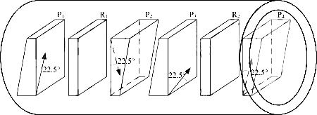
Figure 8 Core structure #2 of a double-stage wedge optical isolator
Let's look at the structure in Figure 8. What happens if the optical axes of wedges P2 and P3 are not strictly perpendicular to each other? The backward light is first split into two rays in wedge P4 and then further split into four rays in P2. Two of the four rays have higher intensity, and their SOP transformations in the four wedges are o→e→o→e and e→o→e→o. These two rays are blocked due to the angular deviation. The other two rays have lower intensity, and their SOP transformations in the four wedges are o→e→e→o and e→o→o→e. SOP transformation means that wedges P2 and P3 can be regarded as parallel plates, while wedges P1 and P4 can be regarded as another parallel plate. The latter two rays pass through the two parallel plates. They maintain the transmission direction and are finally received by the input collimator. Therefore, the isolation is reduced.
Although the intensity of the latter two rays is quite low. The impact on isolation is significant. Assuming that the intersection angle between the P2 and P3 axes is 90°±δ, the intensity of the latter two rays is sin2δ. The relationship between isolation and assembly error δ is shown in Figure 9. When δ is 2° or 1°, the isolation is 35dB or 29dB. In order to obtain the expected 55dB isolation of the double-stage isolator, the assembly error δ is required to be <0.1°, which is quite difficult to produce.
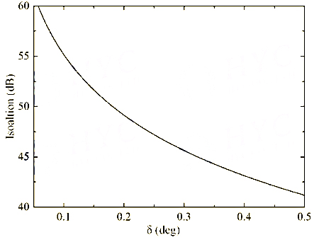
Figure 9 #2 Structure of the double-stage optical isolator isolation and assembly error relationship
- Structure #3
Based on the analysis of the above structure #2, an improved structure of the double-stage optical isolator is given, as shown in Figure 10. The direction of the optical axis is the same as that in Figure 8. The only difference is that all wedges in Figure 8 have the same wedge angle, while the wedges in Figure 10 have different wedge angles. The wedges P1 and P2 in the first stage have a wedge angle of φ1, while the wedges P3 and P4 in the second stage have different wedge angles φ2 [2].
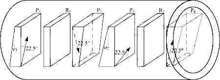
Figure 10 Core structure #3 of a dual-stage wedge-shaped optical isolator
In structure #2 shown in Figure 8, wedges P2(P1) and P3(P4) form parallel plates for two backward light rays through the SOP transformations o→e→e→o and e→o→o→e. Now in Figure 10, the wedge angles of P2(P1) and P3(P4) are different. They can no longer form parallel plates. Therefore, these two rays are also blocked.
The tracing of the two backward light rays is shown in Figure 11. Both the cases in structures #2 and #3 are shown for comparison. Each stage of the isolator core acts as a Wollaston prism for the backward light. In configuration #2 of Figure 11(a), the second stage first angularly separates the two rays. The first stage then turns the two rays to the horizontal direction because the rotation angles ψ1 and ψ2 of the two stages are the same. In configuration #3 of Figure 11(b), the two rays are also first angularly displaced by the second stage and then turned by the first stage. However, the rays cannot return to the horizontal direction because the angles φ1 and φ2 of the wedge angles φ1 and φ2 are different. As shown in Figure 6, the isolation is quite sensitive to the angular displacement. A small difference between Φ1 and Φ2 can produce enough ΔΦ=Φ2-Φ1 to guarantee isolation. Note that there is another factor sin2δ (shown in Figure 9) that helps block the two rays of the SOP transformations of o→e→e→o and e→o→o→e.

Figure 11 Tracing of two rays of o→e→e→o and e→o→o→e SOP transformations
The assembly of the double-stage optical isolator core is shown in Figure 12. The wedge and FR are sandwiched by two quartz substrates with arc-shaped intersections. All components are then loaded into a magnetic ring and fixed with adhesive.

Figure 12 Assembly of the double-stage optical isolator cor

