Design and performance test of a new solar street light controller

Hedy · Dasenic Dec 19,2024 106

The solar street light system is essentially a small independent photovoltaic system, which mainly consists of four parts: solar cell, battery, control circuit and lighting circuit. At present, the solar street light controller is still in the research and development stage. Most of the commercially available controllers use single-chip microcomputer control, which has the disadvantages of complex circuit, high cost and difficult maintenance. In view of these shortcomings, this paper designs a new type of solar LED lighting control circuit, which uses the controllable switch characteristics of TIA31 to realize the switch control of the solar street light system, battery overcharge and over-discharge protection and other functions. The controller is efficient, energy-saving and sensitive, and can meet the requirements of solar street lights in practical applications.
1. Main functions of the controller

(1) Battery overcharge protection function: During the day, the photovoltaic panel charges the battery under the control of the controller. When the battery terminal voltage rises to 14.4V, the controller automatically cuts off the charging circuit to prevent overcharging, protect the battery and extend its life.

(2) Battery over-discharge protection function: At night, the battery supplies power to the LED street light under the control of the controller. When the battery terminal voltage drops to 10.6V, the controller automatically cuts off the LED street light to prevent the battery from over-discharging.

(3) LED street light automatic on-off function and constant current control function: When night falls, the natural light brightness is lower than the outdoor lighting brightness requirement, the controller automatically turns on the solar street light switch, and the battery supplies power to the street light. When there is sufficient natural light during the day, the controller controls the solar street light to automatically turn off. The battery voltage is usually controlled between 10.6V and 14.4V. In order to keep the illumination of the LED street light basically consistent and increase the battery power supply time, the LED street light constant current control circuit is used to control the LED street light current to basically maintain a constant current.

2. Controller hardware design

The solar street light controller circuit designed in this paper is shown in Figure 1.
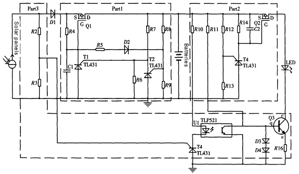
Figure 1 Solar street light controller circuit diagram

2.1 Introduction to TL431 Chip

TL431 is a precision three-terminal shunt diode shunt regulator with good thermal stability produced by Texas Instruments (TI). As shown in Figure 2, TL431 consists of a 2.5V precision reference voltage source, a voltage comparator and an output switch tube. The output voltage of the reference terminal R is compared with the 2.5V precision reference voltage source. When the R terminal voltage VR reaches or exceeds 2.5V, the TL431 cathode to anode direction is immediately turned on. By accurately controlling the R pole signal voltage, the switching state of the cathode to anode direction can be accurately controlled.
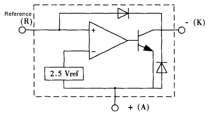
Figure 2 TL431 equivalent functional block diagram

This solar street light controller is designed based on this function of TL431.

2.2 Overcharge protection control circuit design

The battery is an important component of the solar street light system. A protection circuit must be designed to avoid battery overvoltage or undervoltage, thereby extending the battery life. The battery model selected in the design is 12V 7.2AH, and the voltage is required to be maintained at 10.6V~14.4V.

The dotted box Part 1 in Figure 1 is the schematic diagram of the battery overcharge protection control circuit. By reasonably selecting the resistance values ​​of R8 and R9, when the voltage across the battery reaches 14.4V, the reference voltage of T2 just reaches 2.5V, and the voltage between the reference pole and the anode of T1 is less than 2.5V. Therefore, T1 is turned off, so that the P-channel field effect transistor Q1 works in the cut-off region, cutting off the charging circuit to prevent the battery from overcharging.

The circuit uses T2 to control the reference voltage of T1, so that the reference voltage of T1 only appears in the range far greater than or far less than 2.5V, thereby avoiding interference from the solar cell side circuit. In this way, when the battery voltage just reaches 14.4V, the circuit can be completely cut off, increasing the stability and reliability of the protection circuit.

2.3 Over-discharge protection control circuit design

The dotted box Part 2 in Figure 1 gives the schematic diagram of the battery over-discharge protection control circuit. The over-discharge protection control circuit has certain similarities with the over-charge protection control circuit. By reasonably selecting the resistance values ​​of R12 and R13, the opening and closing of T3 can be controlled, thereby preventing the battery from over-discharging and causing the voltage to be lower than 10.6V. This will not be described in detail here.

2.4LED street light control circuit design

The dotted box Part 3 in Figure 1 gives the schematic diagram of the LED street light control circuit, which implements the functions of turning off the light during the day, turning on the light at night, and LED quasi-constant current control.

The specific switching action is mainly realized by T4 (TIA31). When VR≥2.5V, the cathode of T4 is turned on to the anode, thereby controlling the optocoupler switch U1 to turn on, and the NPN transistor Q3 enters the cut-off area, thereby cutting off the LED load from the main circuit and turning off the street light; on the contrary, when VR<2.5V, the transistor works in the saturation area, the LED load is connected to the main circuit through Q3, and the street light is on. Taking advantage of the different open-circuit voltages of solar panels under different light intensities (day and night), R2 and R3 with appropriate resistance values ​​are selected so that the voltage across R3 (i.e., the reference pole voltage of T4) is exactly 2.5V under the light intensity when the street light needs to be turned on or off, and the intelligent switch control of the street light can be realized.

During the process of the battery supplying power to the LED load, due to the clamping effect of diodes D3 and D4, the voltage of the b pole of Q3 remains basically unchanged, and its e pole voltage is also maintained in a relatively stable state, and the current in R16 is basically constant, thereby realizing the quasi-constant current control function of the LED.

In addition, in practical applications, Q2 and Q3 in the controller circuit can be replaced by an AP4511GM chip, which can simplify the circuit and reduce costs.


3. Controller performance test

In order to test the controller, an 18V20W solar panel, a 12V 7.2AH battery, and a 230mA LED lamp were selected to conduct actual tests on the controller.

3.1 Charging performance test

The open circuit voltage of the solar panel changes with the light intensity, so the battery charging curve is also affected by factors such as weather and time. In the experiment, three sunny days were selected, and the charging test was carried out from 10:00 am. The curve of the battery charging by the controller under ideal conditions is shown in Figure 3. In the five hours from 10:00 to 15:00 in a day when the light conditions are good, the battery voltage rises from 10.8V to 14.4V. In fact, the controller has turned off the charging circuit at this time. It can be seen from the charging curve that the controller meets the design requirements of charging control.
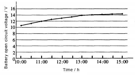
Figure 3 Battery charging curve

3.2 Discharge performance test

In order to obtain a complete discharge curve, the solar panel is covered with a black cloth or the charging circuit is cut off for continuous discharge. The battery discharge curve is shown in Figure 4, where the discharge current is basically maintained at about 230mA. It can be seen that the battery can keep the street light working for 16 hours and automatically shut down at about 10.6V. Its discharge performance meets the design requirements of solar street lights.
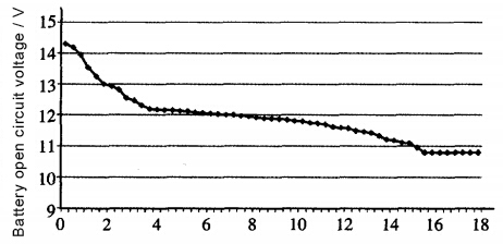
Figure 4 Battery discharge curve

Conclusion

This article summarizes the design of a solar LED street light controller based on TL431. The controller has functions such as overcharge, over-discharge protection, LED quasi-constant current control, and can automatically start and shut down LED street lights according to brightness. Experiments show that the controller can not only meet the control requirements of LED street lights, but also has reliable operation, low cost, and convenient maintenance, and has extremely high promotion value.


  • RFQ